3D print(ed/ing) robot arm part I
To have fun, to explore business opportunities, to learn, to add to scientific knowledge, I'm building a robot arm. The first chapter of the series is about the motor actuator.
Hello.
I'm very excited to start yet another project. The context of building a robot arm is that building a functional robot arm is quite a technical achievement, although there are levels to the degree of functionality and accuracy. Next to that there are many things you can do with a robot arm: it can sort you Lego's, you can use it as an opponent for a game of GO, and in my case it will 3d print, and as a stretch goal, it will print strong composite parts...
If you have an application for a robot arm, usually if you work at a company you will probably be able to purchase an arm that suits the job and focus on your application. However, for me part of the challenge is to grab some affordable components and put my 3d printer to work and voila, hopefully at the end of this series I will have succeeded in building a robot arm.
You can find existing home built robot arms, to categorise them some are really entry level using small servo motors that come with a potentiometer that gives it a movement of roughly a half turn each way. This entry level arm will not be suitable for 3d printing because its accuracy falls short of what you need for 3d printing. If your arm is 80cm long and you need to travel 0.1mm then you need to rotate your joint 0.007 degrees. Maybe I am yet unaware of the inverse kinematics calculations but this 0.007 degrees would be worst case.
If you can spend a few thousands that you get a small arm with stronger more accurate motors that can postentially be used for 3d printing. But we are talking a few thousands of dollars, that still quite an investment.
But the idea for my arm is that if your budget is constrained you can still contribute to scientific research in the field of 3d printing. Basically it's putting tech in the hands of students and hobbyists, letting them experiment with the hardware and software at a professional level not before possible. Ok, we set a goal...
This first chapter is about the actuators, now as I mentioned those servo motors are nice if you need to control an airfoil or something simple like the steering wheel of a RC car, but to get some real accuracy a stepper motor together with a gear reducer is the way to go. I will explain the actuator I found on YouTube and then designed and customised the idea in Fusion 360.

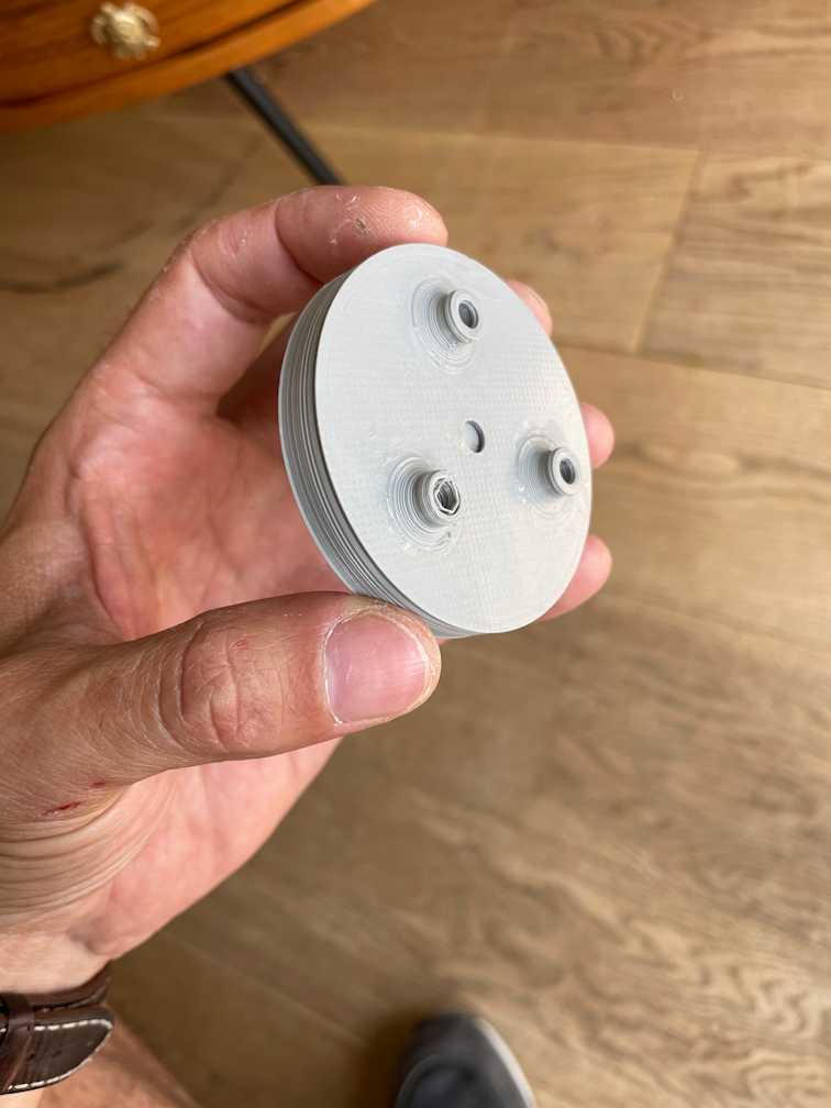
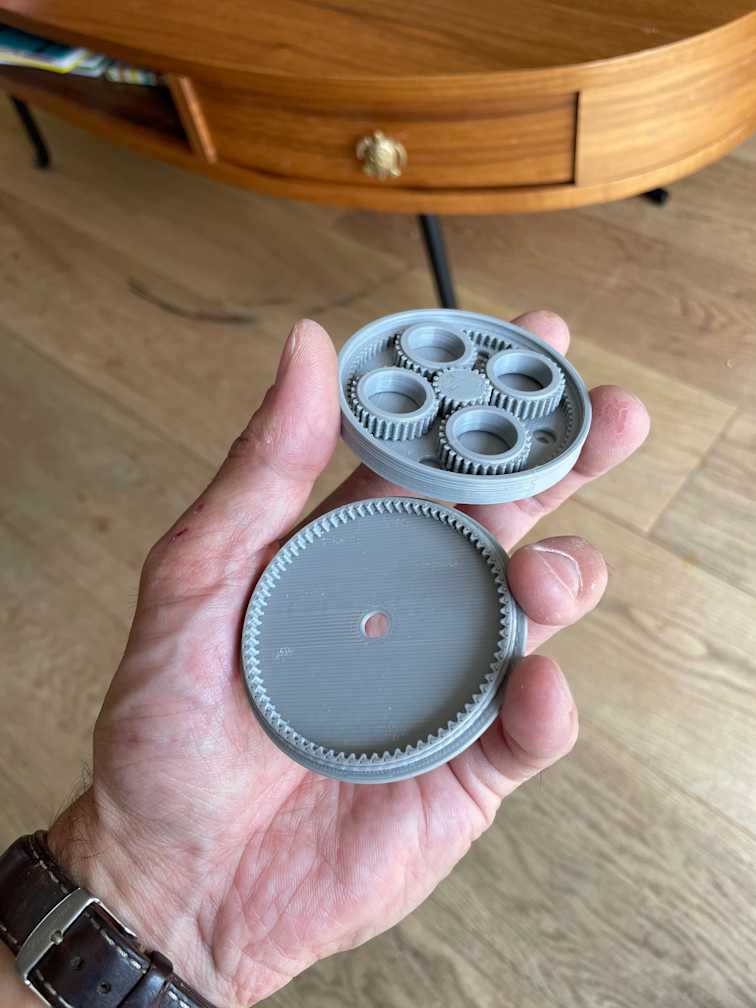
The first stage of the actuator is a planetary gear setup. By accident I found out a combination of truly 'magic' numbers for the number of teeth of the sun, the planets, and the outer ring. If the sun gear is 20 teeth, the planets are 30 teeth and the outer ring is 80 teeth, then the reduction is a perfect 1 : 5. I knew that when the sun is smaller than the planets the reduction is higher so I used this simulator to come up with my magical combination. The second stage of the actuator is a second outer ring is lending a principle from the harmonic drive, in the sense that the planets are driving a second outer ring that has a reduced number of teeth (76 in my case). In this way for each quarter turn of the planets, the driven ring turn 1 tooth. So the total reduction is 1 : 5 x 4 : 80 = 1 : 100 !! That's exactly one to one hundred. Very nice!

Coming back to my other 'magic' number 0.007 degrees, the question is wether this actuator and stepper motor can do it. Well, the stepper has a step of 1.8 degrees but you can go more precise using substeps of 1/8 step. So 1/8 step of 1.8 degrees divided by on hundred would be 0.00225. Incredible! in theory our arm will be capable of accurate enough movement to 3d print something :)) If you balance out the actual movement (a 3d printed actuator might have som noise in its movement) with the fact that the arm is never going to be fully extended when printing something we are looking good I think.
See you in the next chapter!