3D print(ed/ing) Robot arm part II (UPDATE)
I describe my next steps in the process of making an accurate robotic arm that can 3d print.
The actuator at the right print settings proved to be quite smooth and gave me confidence in the success of the arm. I lubricated the gears with some Vaseline (petroleum jelly) which did the job and gave the actuator a nice sound when rotated. After 3d printing the actuator, it was time to tackle the arm itself.
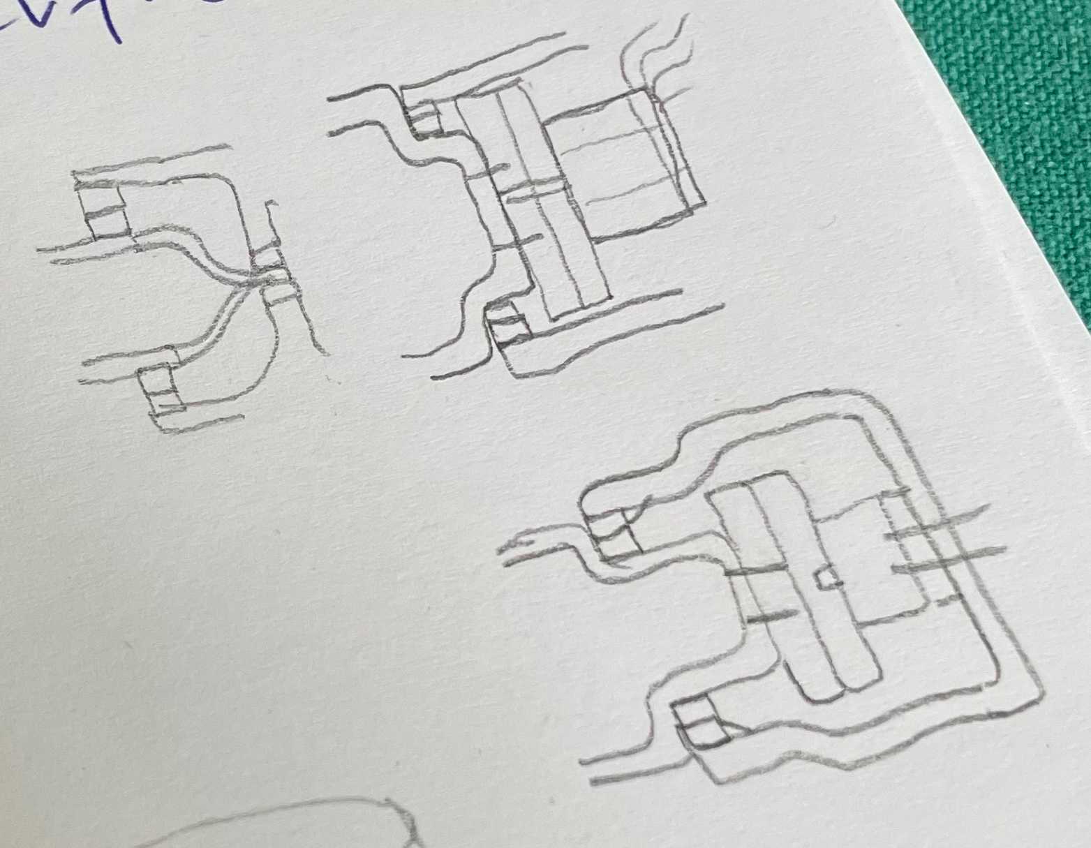
My challenge is to make and arm that is very precise although it is made from mostly printed pla. For every joint I have a 65mm x 50mm x 7mm bearing that should give a very accurate rotation. My fear was that radially they would be good enough, but that they would be able to wiggle a bit. To counter any wiggling motion I designed the rotational transmission in a way that there is an 'arm' to the rotation as shown in the sketch below. The longer this 'arm' length is, the less there is any possible wiggle. Thanks to my physics teacher for this arm theory :)

The design of the arm parts is modular, every joint is based on the same basic parts, the part with the motor, the actuator in the middle and the the bearing and the actual rotating part. I printed the first part that will be able to be mounted to a platform using screws.
I'm continuing this journey with a course on Udemy to learn ROS2 and use a raspberry pi to control my robot. I stumbled on this master thesis which is about robotic arms that can 3d print. I will continue assembling the first part and after I finalise the tolerances I will try to hook up the motor to the raspberry with a stepper driver. Exciting stuff...
UPDATE:
When connecting the 3d printed actuator to a motor and using a python script on a Raspberry pi to control the motor, the result was very disappointing. Mainly because there was an awful amount of movement noise in the rotation. Partly relieved that I at least had some resolution, I threw the concept of the planetary harmonic compound away.
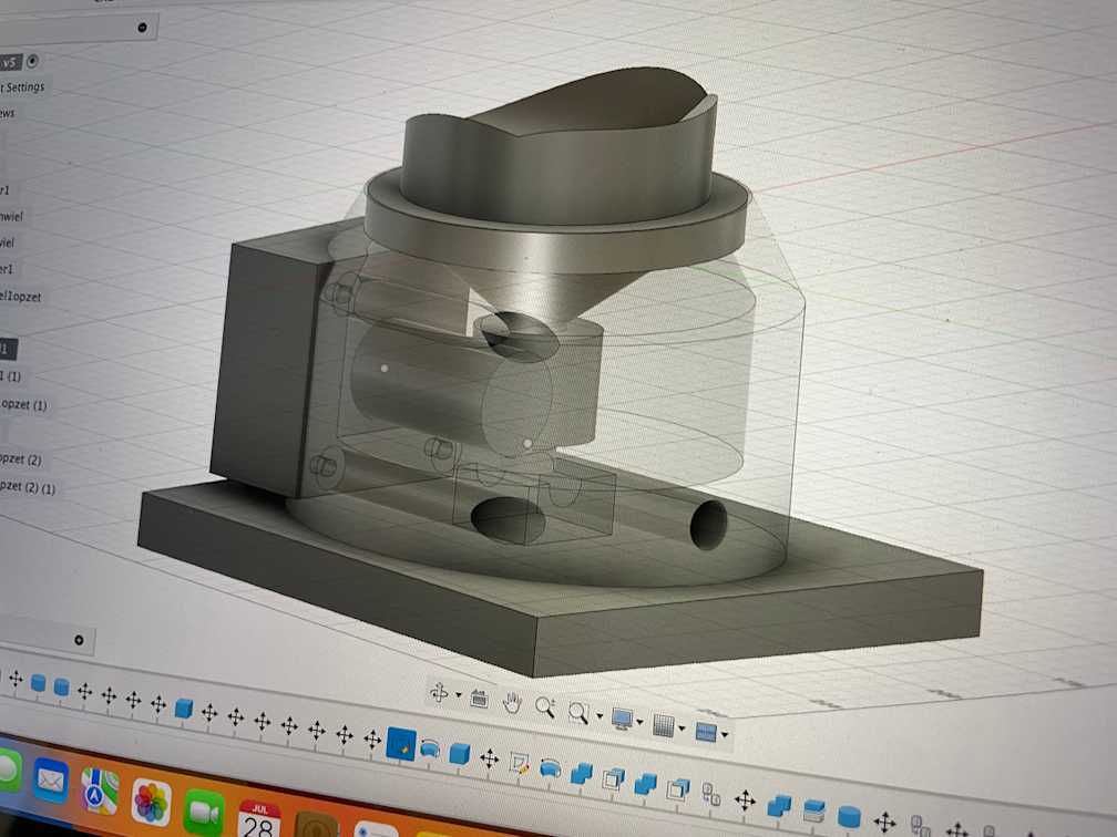
I did some googling and ChatGPT-ing and one of the solutions for a large gear reduction is using a worm gear. So I ordered a couple of worm gears from ALiExpress. I went ahead and sketched up a new design in Fusion 360, this time the stepper motor is directed perpendicular to the rotational axis.

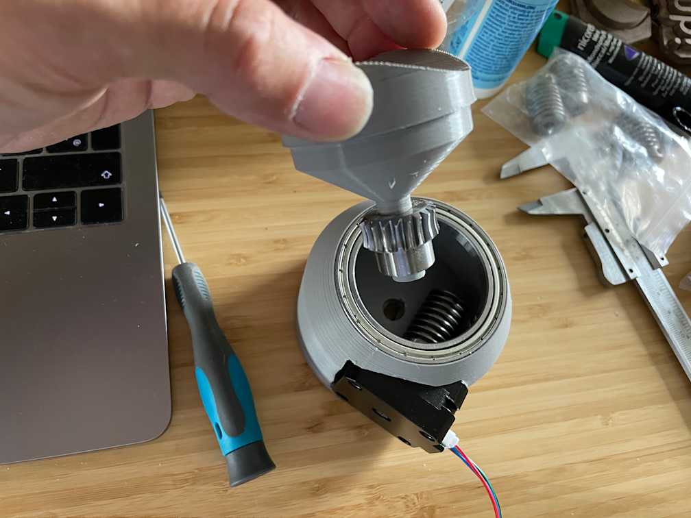
Then I 3d printed the parts and was happy that with a horizontal expansion of -0.1 for the big part, the large ring bearing fit pretty snug. The smaller part was printed without horizontal expansion as mostly you only need that for things that have to fit in holes.
Another test on the Raspberry pi pointed out that:
stepper motors are underpowered
the design needs a few tweaks
the motion was very satisfying using the worm gear

That's it for the update, cheers!! ☕️
